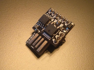
Playing with junk: the SN29764 (LM1017) 4-bit binary 7-segment display driver.
While digging through my parts bins looking for my spare arduino nano I came across a boart that I was keeping solely for the 7-segment display that was attached to it. I noticed that there also was an IC marked SN29764 on the board and got curious. After some googling I came up with a LM1017 datasheet, which states that it's an equivalent to the SN29764.
Basically what this IC does is it takes a 4-bit binary number through pins 2, 3, 4 and 5, and displays that number on a 7-segment display. Since this IC was made to display channels on a TV it doesn't display the number 0 but it displays numbers from 1 to 16. Pulling pin 1 down sets the display to full brightness.
I find it quite interesting that there would be a dedicated IC for this application but the world proves to be quite large and technology has sure advanced since the old days. There isn't a date code I can read on the IC but it might very well be older than me even, well I'm not even that old so it very likely is older than me, to be fair.
But anyways, I want to make it display something, moreover I want to make it count. But first I need to find out how to connect this thing to get anything out of it. First I checked the datasheet but it doesn't do a good job of showing where to connect the ground in the connection diagram. The datasheet I found only has 6 pages but the page number seems to indicate that there are 11 in total so there might be more info left out. Through trial and error I found out that ground pin on the IC is pin 6 and was able to see it work for the first time. After some playing around I noticed that the inputs on the input have pullups on them so if left floating they will be HIGH by default.
Ok, so now that I've confirmed that it works it was time to make it count. For this I used my spare arduino nano, which I managed to find along with this display board. I made a quick and dirty sketch where it counts up from 1 to 16 and then resets back to 1 and counts up again. The variable is dismantled through bitwise operations and used to control the outputs through digitalWrite() functions. And voila! The display now counts from 1 to 16.
Of course I don't have any use for this board other than entertainment value and I'll end up just desoldering the 7-segment display and tossing the rest away. But I think this was a fun excercise nonetheless.
Anyways that's it for now, thanks for visiting my blog and, before I forget, here's the example code:
char counter;
#define A 2 //digital pins
#define B 3
#define C 4
#define D 5
void setup() {
// put your setup code here, to run once:
pinMode(A, OUTPUT);
pinMode(B, OUTPUT);
pinMode(C, OUTPUT);
pinMode(D, OUTPUT);
}
void loop() {
// put your main code here, to run repeatedly:
digitalWrite(A, counter & 0b0001);
digitalWrite(B, (counter & 0b0010) >> 1);
digitalWrite(C, (counter & 0b0100) >> 2);
digitalWrite(D, (counter & 0b1000) >> 3);
digitalWrite(13, 1);
delay(500);
digitalWrite(13, 0);
delay(500);
counter ++;
if (counter > 16) counter = 1;
}


Komentarai
Rašyti komentarą