Infrared RGB LED controller using Digispark (Attiny85).
While building a PC I thought I'd toss in some RGB to see how it looks. Problem is I had lost the receiver. Bummer! But I still had the remote, so I decided to make my own RGB controller.
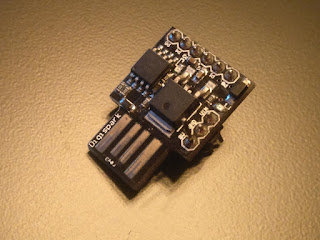
For this project I chose to use the Digispark, which is like an arduino but is based on the Attiny85. A regular arduino like the arduino nano, or even any other microcontroller like the STM32 "blue pill" can be used for this project. In this case I wanted a small microcontroller, something like an atmega328p would have been a bit of an overkill.

Before I could make my microcontroller do anything I had to find out what my remote was transmitting. To do this I used my OWON VDS1022 USB oscilloscope, with which I saved the samples of the waveform in a .txt file. The bitrate of the signal transmitted by the remote is quite low so something like a DIY audiojack oscilloscope (look it up) would work also.
The .txt file then was passed through a matlab script I quickly put together to decode the signal into a hex code. This hex code is what I needed, it can be used in the code in the microcontroller to know what do to when it receives that particular signal.
I based my program on an LED blink example using internal timer interrupt in the attiny85 found in this forum thread: https://forum.arduino.cc/index.php?topic=163393.15
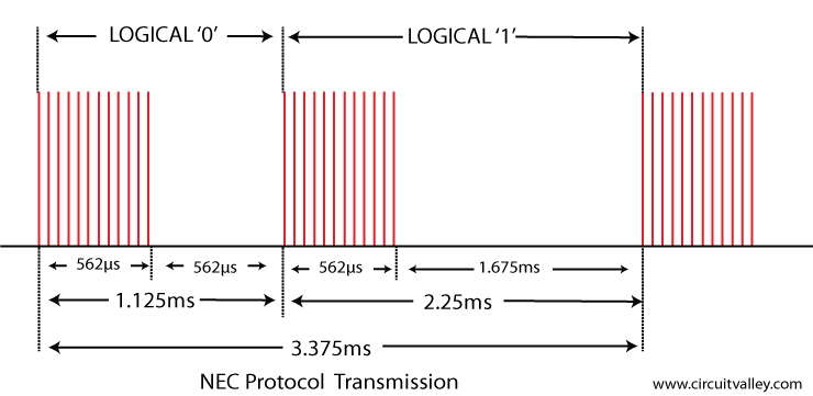
The code I wrote is rather simple. It works by checking the state of the input pin every now and then and when something is received it calculates the length of the pulses with the help of the timer interrupt. The signal sent by these IR semotes is based on the NEC IR protocol.
And as you can see telling logical 0 apart from a logical 1 is as easy as checking which one of them is longer. There's also the start bit, which is even longer, but we can assume that everything slightly longer than a logical 1 is a start bit. The multiple sharp pulses seen in the picture above are not relevant, because they get smoothed out by the IR receiver chip and turned into a solid pulse. In my code I count the time between each time the state of the input pin changes from high to low. The length of the pulse is counted in the times the timer interrupt was called. Bitwise operations are used to reconstruct the signal into a hex number. This hex number is then compared to the hex numbers in the code and if a match is found the PWM for the LED outputs gets set accordingly. There are not enough PWM outputs on the attiny85 to control all three colors, so I went with a software PWM, which worked out very well.
I think the code is quite self-explanatory. Pin P0 is the digital input from the IR receiver chip. Pins P1, P2 and P3 are the PWM output pins for the LED driver transistors. In my case I connected the outputs to TL431 voltage reference IC's, since they can also be used as low current MOSFETs with a 2.5V gate treshold voltage. I would recommend logic level MOSFET's or BJT's instead of TL431's, because they can handle higher current and drive more LEDs. In my case TL431's were on hand and the LED strip was very short, so why not.

Some things I found out during this project are that debugging an 8-pin microcontroller is not exactly easy but also quite doable. Also not all 3-pin IR receiver chips have the same pinout. As I have found out the hard way. The one I pulled out from an old TV had a different pinout and the first time I plugged it in literal smoke started coming out of it. Fortunately after I shuffled the wires around the IR receiver started working as if it had never released any smoke.
In the process of writing the code for this project I found my RGB controller but I had another remote for RGB flower pot lights, so I used that remote instead. But regardless I was able to finish the code and make it work, and honestly it surprised me how suddenly it changed from not working to 100% working with just some simple debugging. I was expecting that once I got it working it would maybe glitch sometimes but it worked flawlessly every time.
The C++ code for the digispark is below, but proceed at your own risk as it's very messy 😅. But adding more modes or colors is very easy and as you can see in the code every color has it's own macro to represent the hex code that the remote transmits along with it's case in the switch statement. And the color brightness is adjusted from 0 (0%) to 255 (100%). The attiny85 sports 8k of FLASH memory, meaning that a lot of code can be crammed into this tiny little thing. Granted, some of the code space is taken up by the bootloader but there's still plenty space left. And of course this little device is not limited to just controlling LED's and it will do anything you code it to do.
That's it for now, thanks for reading.
/*
* OLIMEXINO tiny85_blink_by_timer_interrupt.ino
* Code by BrimmingIdeas at blogger.com
*/
#include <avr/io.h>
#include <avr/interrupt.h>
int8_t count, tick, flipflop;
uint8_t LED_R = 0, LED_G = 0, LED_B = 0, LED_tick, bit_counter;
uint32_t data_bits = 0x00FF02FD;
//------defines for unknown remote-------------------------
//#define RED1 0x00F720DF
#define RED1 0x00FFABCD
//------defines for lumapots remote----------
#define RED 0x00FFE01F
#define GREEN 0x00FFA857
#define BLUE 0x00FF906F
#define CYAN 0x00FF30CF
#define MAGENTA 0x00FF18E7
#define LBLUE 0x00FF7A85
#define WHITE 0x00FF38C7
#define ONOFF 0x00FF02FD
#define R_pinout PINB1
#define G_pinout PINB2
#define B_pinout PINB3
//-------
#define Brightness 127 // currently unused
void LED_control ();
void setup()
{
// Disable global interrupts before initialization
cli();
//initialize output;
DDRB |= (1<<PINB1); // R
DDRB |= (1<<PINB2); // G
DDRB |= (1<<PINB3); // B
DDRB |= (1<<PINB4); // test pin for debugging
//initialize the timer0
TCCR0A = (1<<WGM01); // Put timer0 in CTC mode and clear other bits
TCCR0B = (1<<CS02) ; // Timer0 prescaling 256 and clearing other bits
TIMSK |= (1<<OCIE0A); // enable timer1 compare interrupt
//set the timer0 count
OCR0A = 2; // Count 2 cycles before calling ISR interrupt
//initialize global interrupts before beginning loop
sei();
}
void loop()
{
}
ISR(TIM0_COMPA_vect) {
LED_tick++; // probably unused variable
tick++;
if ( (PINB & (1 << PINB0)) == (1 << PINB0) && flipflop == 0){ //checking input pin
flipflop = 1;
bit_counter++;
if (bit_counter > 32){ // data array ready for LED ctrl
LED_control (); // get PWM variables
}
tick = 0;
}
if ( (PINB & (1 << PINB0)) != (1 << PINB0) && flipflop == 1 ){ //checking input pin
flipflop = 0;
if (tick > 25){ // logic 1
data_bits = (data_bits << 1) | 1; // bitwise shift to add 1 to array
//data_bits = data_bits << 1;
}
if (tick > 40){ // transmit start
bit_counter = 0;
data_bits = data_bits % 0x00; // clear data array
}
if (tick < 25){ // logic 0
data_bits = data_bits << 1; // bitwise shift to add 0 to array
}
tick = 0;
}
// ------------ SW PWM for LED control ----
if ( LED_tick < LED_R ){
PORTB |= (1 << R_pinout);
}
else PORTB &= ~(1 << R_pinout);
if ( LED_tick < LED_G ){
PORTB |= (1 << G_pinout);
}
else PORTB &= ~(1 << G_pinout);
if ( LED_tick < LED_B ){
PORTB |= (1 << B_pinout);
}
else PORTB &= ~(1 << B_pinout);
}
void LED_control (){
switch ( data_bits ){
case 0x00FFABCD: // red
LED_R = 255;
LED_G = 0;
LED_B = 0;
break;
case RED:
LED_R = 255;
LED_G = 0;
LED_B = 0;
break;
case GREEN:
LED_R = 0;
LED_G = 255;
LED_B = 0;
break;
case BLUE:
LED_R = 0;
LED_G = 0;
LED_B = 255;
break;
case CYAN:
LED_R = 0;
LED_G = 255;
LED_B = 255;
break;
case MAGENTA:
LED_R = 255;
LED_G = 0;
LED_B = 255;
break;
case LBLUE:
LED_R = 0;
LED_G = 127;
LED_B = 255;
break;
case WHITE:
LED_R = 255;
LED_G = 255;
LED_B = 255;
break;
case ONOFF:
LED_R = 0;
LED_G = 0;
LED_B = 0;
break;
}
}


Komentarai
Rašyti komentarą