Modding a laptop power brick into a lithium pack charger and some Manhattan style prototyping.
I've built a few 4S lithium battery packs but I didn't have a charger. So I decided to make one by modifying a switch-mode power supply. The power supply I used had a special plug on it with three pins. One of them being a sense pin to change the voltage. On this plug an adapter would connect, which would have a resistor in it that would change the voltage on the output. This power supply is nothing special, though. All this wire does is go straight to the REF pin on the TL431 reference IC inside. How do I know that? Because I accidentally blew the TL431 and had to pull the power supply apart to replace it. If you're willing to pull apart a laptop power supply you can add this wire to the TL431 reference and you'll have basically the same thing I have.
Opening them can be a pain. Mike from mikeselectricstuff shared in one of his youtube videos that whacking the weld/glue seam on the power supply will crack the joint and the power supply will come apart. But I've had mixed results with this method. Seems like it works better on cheaper power supplies. and the more expensive ones have to whacked so hard that the inside components take a hit also, so it's not ideal. But carefully cutting the seam until the case pops open works also.
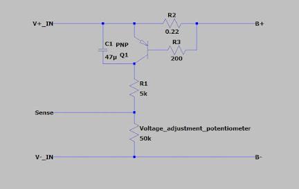
I decided to take advantage of the sense pin on this power supply and implement a current and voltage control, which are the necessary to charge lithium cells. The way this power supply controls the voltage on the output was quite simple. As the voltage on the sense pin went up, the voltage on the output went down. Meaning that when I reach my desired current I need something to pull that voltage up. To do this I used a PNP transistor and a 0.22 Ohm current shunt resistor. And how this works is that when the voltage on the shunt exceeds 0.6V or so it activates the PNP transistor, which channels some current into the sense pin and decreases the voltage on the output. The voltage on the shunt is directly proportional to the current going through it, so this circuit ends up limiting the current. This exact method is used in some very old Nokia chargers and it works well but it has its limitations. The advantage of this circuit is that it's very simple and straight forward. Some other components were added to make the circuit more stable and to reduce the chances of it blowing up. For example a base resistor was added to the transistor to limit any inrush current. A capacitor was added across the transistor to stop oscillations in the power supply because it makes an annoying noise otherwise. The collector resistor was added to limit the effect of the transistor on the output voltage to prevent undershoot and a trim potentiometer was added from this resistor to ground to set the output voltage. This particular power supply sits at 15.6V when nothing is connected, yours might be different so you might have to connect a resistor in parallel to the capacitor on the PNP transistor to bring the voltage down.
To build this circuit I decided to take a piece of FR4 and built it in the Manhattan style, which I learned from watching W2AEW's YT channel. When building a circuit in the Manhattan style you take a piece of FR4, which acts as your base, and glue small pieces of FR4 on top to make islands, which act as your nodes. In my case I didn't have any super glue left so I took a different approach. I took an old wood drill and regruond it so that it would only score the copper around its edges. This way I could make islands on the FR4, which acted as my nodes. The center spike remained on the drill to hold it stable, which makes a small dimple in the center of the island but it gets filled with solder anyways.


Komentarai
Rašyti komentarą