Making my homemade spot welder stop blowing up. Or how I made my homemade battery tab spot welder.
I got a defective Airwheels pack from my internship and it had 64 18650 cells inside, of which 16 were dead but the remainig 48 were still good. And I saw this as a great opportunity to make a big lithium battery pack for other projects, like my homemade electric scooter, for example.
These packs are most often welded together with spot welders but I don't have one. Previously I used to solder to salvaged batteries. When I salvage batteries I leave a piece of the nickel strip on them so that I can solder to it later. But for a big pack soldering would take ages, not to mention how tedious it would be trying to get a good solder joint without cooking the cell. Oh and don't forget the mountain of solder it would take and all the fumes you would be huffing the entire time. Because of this I decided that it's finally time to build myself a battery tab spot welder.
I've previously explored the world of spot welders many years ago and even experimented with CD spot welders a little. Unfortunately, at the time I had neither the know-how, nor the materials needed to make a spot welder. I've also onsidered making a spot welder with a swiching power supply. The basic idea was that a ZVS circuit would drive the primary and the secondary would be like a single turn of beefy copper. This idea also didn't go far, because finding a suitable ferrite core is pretty hard and getting a single turn primary to couple to the secondary efficiently is also not a trivial matter. What I settled on is a MOSFET based spot welder that uses a car battery to supply the welding current.
First thing to make was the controller. At first I considered just using some ransistor based timer, or something with a 555, or an opamp/comparator. I quickly realized that such a circuit would be very limited in its functionality so I went with an arduino instead. Since I was using an arduino I also added a 16x2 character LCD. I had also recently received some rotary encoders so I added one to the controller as well. The LCD was controlled through a standard arduino library and the encoder was sensed with an interrupt. Timing was controlled by counting milliseconds with the millis() function. There are better ways to do this because arduino code tends to be quite bloated but for simple stuff like this it works perfectly well.
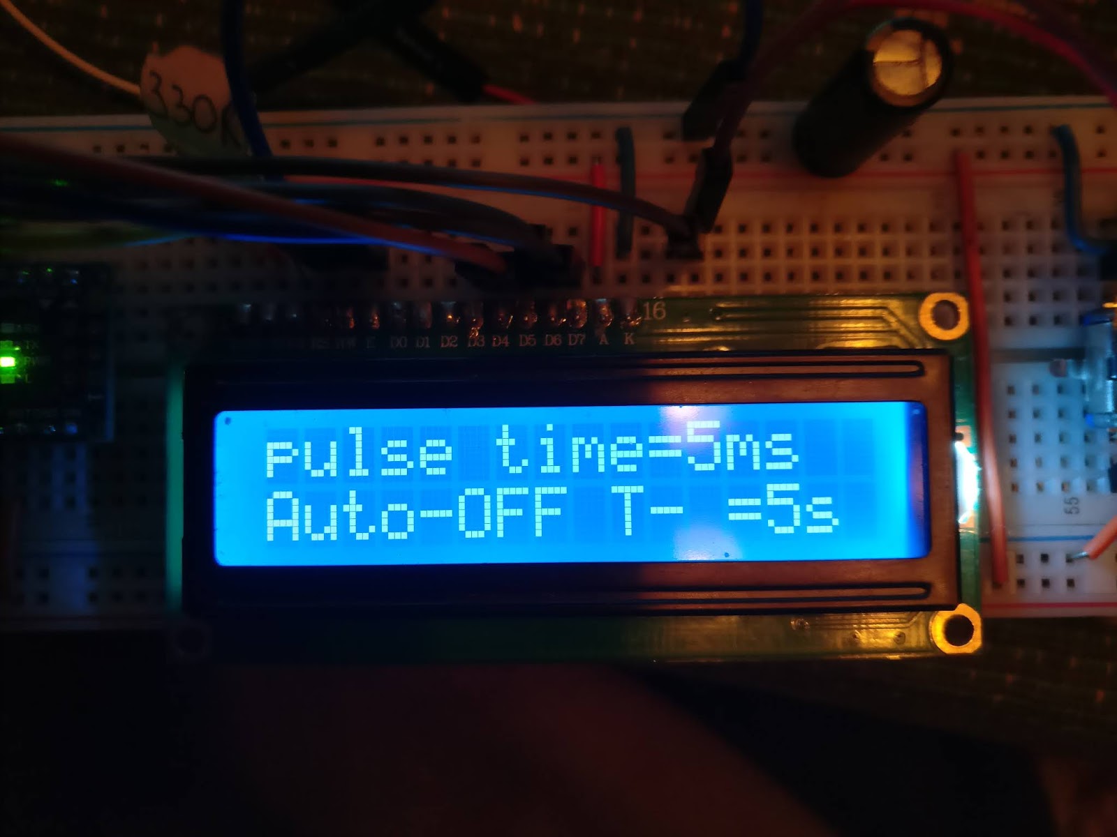
In code I added three settings to change. First is the timer in milliseconds, which decides how long the wending pulse is. Second is the ON/OFF select for the auto function. Many cheap welder kits have this function where they weld automatically once you touch your electrodes on the nickel strip. The third setting was the "T-" setting for the auto function. This setting controls the time that the welder waits before welding on auto mode. If you set T- to 3 seconds the welder would wait 3 seconds before it welds, after the electrodes touch the nickel strip. After some debugging I managed to make the welder work but the auto function still has this bug where it occasionally fires immediately after the electrodes touch on the nickel, which is not great. I also added a pedal input so I didn't really bother fixing the auto mode bug because I'll be using the pedal only. The auto mode was secondary.
Once the code was working I got to making the gate driver. For this I made a simple gate driver circuit with three transistors.

It's a pretty simple and effective circuit. The top PNP transistor transistor is activated by the NPN transistor below it. When it's activated the gates of the MOSFETs are charged up. Once this transistor turns off the bottom PNP transitor automatically discharges the gates and turns the MOSFETs off. The single 4k7 resistor is there to keep the gate discharged when it's disconnected from the gate driver and stays on the MOSFET assembly. This circuit requires both of the PNP transistors to be pretty beefy. I used transistors that can handle 3A continuous, but peak current handling capability is also important. It's also important to have high current gain, the transistors I chose have a hFE of about 300. This means that the base current gets amplified about 300 times. High current PNP transistors can be hard to find so if this circuit is flipped over it can also be made to work with NPN transistors instead. And uses one less transistor.

Once we have the gate driver it's time to build the MOSFET assembly. This MOSFET assembly will carry the full welding current so it's important to make it reasonably heavy duty. This means that both the conductors used and the MOSFETs have to be pretty chunky. For my first time I completely ignored the latter and used whatever salvaged transistors I could find. I pulled my transistors from DELL and other motherboard VRM's and these do tend to be pretty good transistors actually. But for a welder they were not good enough as is shown by the pile of blown MOSFETs I have now accumulated. Below are a couple examples.


For my conductors I used a flattened copper pipe. These tend to be an inexpensive and widely available source of copper. For the base material I chose a piece of MDF that was left over from my shelf. At this point I was basically cobbling together stuff just to try the thing out. MOSFETs were soldered to the copper bars directly and a piece of perforated proto-board was used to connect the gates together through a 10 Ohm resistor for each gate. The copper bars were joined together with M6 bolts.


I used pieces from the same copper bar to also make the electrodes. Since these pieces were left over I could make more efficient use of my materials. But in reality they were too clumsy and not that practical. I later made electrode holders with different shaped electrodes.

To supply the welding current I first used the old lead acid battery from my car. This battery is very weak and can barely do any work anymore. During my tests I could kind of sort of make welds but the battery would quickly discharge and the welding current would keep dropping constantly. To remedy this I hooked up a charger to keep the battery topped up as much as possible. But after I topped the battery up was when my MOSFETs blew. Seems the current, when the battery was charged up, was too high, even though the battery itself is quite old and weak, meaning that these MOSFETs would certainly not handle a better battery, which I would have to use if I wanted more consistent welds. I turned to aliexpress to order some MOSFETs. Aliexpress is not a reliable source of high power semiconductors as it is flooded with fakes as I've already found out, but some sellers can be found that have good quality components. If fakes are received you can push for a refund and most of the time get your money back, so in the end the only thing wasted is your time and perhaps the shipping cost, which not all sellers agree to cover for. In my case I ordered 10 pieces each of IRL3803 and IRF1324 MOSFETs from one seller and 10 IRF1404's from another. The IRF1404 blew up immediately and once I cracked them open I found out that the silicon die inside is tiny. Compared to a RU8590 that I blew previously these transistors would not handle the 202A peak current as stated in their datasheet.

And of course, whenever I make such findings I am sure to post them as a review in the listing to let others know that these are indeed counterfeit. And after I found this out I decided to crack open one of the other MOSFETs as well, after all it would take a lot less time to break one open than to replace ten blown ones. And what I've found out was that the IRL3803's were also fake but the IRF1324 were genuine. And this presented a weird problem because both were purchased from the same seller, meaning that even if you receive genuine parts from the seller, there's no guarantee that everything they sell is genuine. In this case the seller was quite adamant in defending their position stating that there's "nothing wrong with the product" and the dispute even had to be escalated. After I submitted the enough evidence that these are counterfeit I managed to sway aliexpress's favor to my side and got my refund. And that makes me wonder whether the seller themselves really believed that the parts they were selling are genuine?
I found myself ordering parts from mouser so I dropped 10 DMT4003's in my basket while I was at it so that I would have some MOSFET's from a trusted supplier. And once these MOSFETs arrived I decided that my old MOSFET assembly was a bit too janky so I made a new one on a piece of double sided FR4. Since the copper layer is pretty thin on these boards I also added copper bus bars on the edges to carry the current. Soldering MOSFETs on a large copper base was tedious so I mounted these MOSFETs with M3 nuts and bolts. Source pins were connected the same way, while the gate pins would go up to connect to a proto-board, which held the 10Ohm gate resistors. Since the board was double sided MOSFETs were mounted on both sides.

This time the MOSFETs could handle my car battery in any state and I was starting to feel hopeful. And at the same time I hit yet another bottleneck. I already mentioned that the battery was weak, but now that I could test the welder out fully without the MOSFET assembly blowing up is when I found out just how bad it really is. Even when keeping the battery topped up with the charger I could not make more than 10 weld attempts without it going completely flat, and this will not work if I want to use this welder for anything. Therefore I started looking for better batteries and decided to use a 95Ah 850A "Panther" brand battery I had laying around.

This battery is practically new but it has one major problem - one of the cells is shorted. This hapened when my dad's Mercedes' decided to kill the battery in the dead of the winder and the battery then froze up and once it froze is when the cells got deformed and one of them shorted out. But that's one one cell out of five, meaning that if I bypass the bad cell I can still use the battery as a 10V battery instead. And since during welding only the current matters this would still work with my welder. I should also mention that tampering with batteries is dangerous. Lead acid batteries are, as the name suggests, filled with lead and acid, both of which are dangerous substances. When modifying a battery you are doing so at your own risk.
After I modded the battery I hooked it up to my welder and upon the first weld I immediately found how ferocious it really is because it immediately blew a hole in the utility blade I was trying to weld just as a test. The current was massive, and it only took about three weld attempts before my MOSFET's blew up. At this point I decided that it's time to stop playing games before I bury myself in a pile of blown MOSFETs. And started testing stuff out with a little more forethought.
First was the switching time of my gate driver. What I want is for it to switch as fast as possible since between the ON and OFF states is where the region of max power dissipation lies. To test this I used my OWON VDS1022 oscilloscope and I found out that my gate drive signal was not great but also not terrible. Rise and fall times were in the range of 1µs. Ideally what you want is for them to be below 100ns but let's not forget that we're driving a large bank of MOSFETs so getting fast rise and fall times is hard.
Regardless, there was an improvement to be made to the low side transistor. I added an NPN transistor below the PNP transistor to form an SCR and a schottky diode to limit the base current. This helped reduce the fall time to below 600ns. After some testing with LTspice I found out that getting edges below 100ns is impossible due to the gate resistors, but those are important to keep the MOSFETs from oscillating. So I decided that I had reached the point of deminishing returns and that my gate drive circuit is adequate to drive my MOSFETs.


At this point I also realized that if you squint hard enough my welder is just a huge boost converter, meaning that when it switches off there's a huge voltage spike that is likely to damage my MOSFETs. And this makes sense, because how else does a battery rated for 850A blow a MOSFET assembly that should be able to handle 2000A continuous? (well actually there are many reasons why that would happen, but I digress) I was actually already aware of this issue earlier but wishful thinking led me to not use any over-voltage protection for my MOSFETs. After all most of the cheap ebay kits don't have any protection either. Yet when simulating with LTspice I found out that the voltage spike is quite substantial and can reach well over 300V - yikes!
To handle the kind of overvoltage that this welder produces you need a beefy snubber. Consider that the wire is an inductor, so it resists changes in current, so when your MOSFETs try to shut off while there's 1000A flowing, for a short while your snubber will need to handle the same current. Fortunately this current will never exceed the welding current and it's only a peak current, which makes it a little easier.
Most often, in these welders, the voltage spike is redirected back into the battery by a diode. I tried this out by adding a couple 80CPQ150 diodes that I had left over from another project. These should be able to handle the peak welding current. But during my tests with a car headlight bulb as a load I noticed that they hardly do anything at all and my voltage still spikes to upwards of 40V. At this point I had replaced my blown DMT4003's with the IRF1324's I'd bought from aliexpress. The IRF1324 is only rated for 24V so 40V is still way too high and risks causing damage to my MOSFETs. Also notice the ringing in the voltage, which can cause oscillation due to the Miller effect.


What I decided to do is to make my MOSFETs fight for themselves. By connecting a zener and a schottky diode in series and inserting them between the gate and the drain pins I can redirect the voltage pulse to the gate causing the MOSFET to turn on and shunt it. The value of the zener diode is chosen appropriately so that it's just higher than the supply voltage, so that MOSFETs turn on only when the voltage spike is present, otherwise they would be on all the time. With this mod the MOSFETs basically eat their own overvoltage so you don't have to use any transorbs or huge snubber circuits. LTspice simulation shows that this mod works perfectly well but the MOSFETs will eperience peak power dissipation of several kW. This is fine because the total energy dissipation per pulse only increases by about 30mJ for each MOSFET.


Next step was to add this to all of the MOSFETs, which is exactly what I did. Since the peak current through the zener diodes can be quite high I added two in parallel for each group of 5 MOSFETs. Each MOSFET gate received it's own schottky diode. Also I should mention that using a schottky diode is not strictly necessary. What you need is a fast diode capable of handling modest current so the venerable 1N4148 would work also.

After the mod was complete I switched to a bigger load, which was a 0.33Ohm ceramic resistor. The welding pulses were brief so the resistor handled the power dissipation just fine. During the test I noticed that my voltage spike gets completely squashed and the circuit behaves as it should.

At this point I was full of newfound confidence but before I could do my first true welding test I had to consider one more thing - the peak current. When first making the welder I used quite chunky 16sqmm welding cable to connect everything together and also kept the wire as short as possible. There were no other reasons behind this decision other than I wanted to keep the resistance of the loop as low as possible. But as it turns out I might have overdone it and created a situation where the current is basically unlimited and may far exceed the 850A battery rating. So I decided to do some calculations. A battery like mine has about 5mOhms of internal series resistance and the approximately 130cm of welding cable I used has about 1.4mOhms of resistance. So at 10V that would produce a *drum roll please* over 1.5kA! I thought this was too much and wanted to reduce the current to just below 1kA. To do this I bought 2m of 6sqmm copper wire, which should increase the total resistance to just below 11mOhms, which should limit the peak current to around 900A. The much thinner cable is also not as stiff so handling the electrodes should become easier.

Speaking of electrodes. For my electrodes I used some 6sqmm solid copper wire. To hold this wire I made electrode holders out of some 10x10mm aluminum bar. The electrodes (a.k.a. "needles") are clamped in the aluminum holder with a screw. I made these holders by drilling a 3mm hole in the end of the bar, keeping it close to the edge. Then I sawed the bar lengthways right through the hole but not all the way through. After that I added a screw that would close this slit and clamp the electrode in the aluminum holder. This allows me to not only change the electrodes but to also adjust them.

And now that everything seemed like it should work I could finally test out my welder. All tests were done with an eye kept closely to the oscilloscope trace and constantly checking for anomalies. If these MOSFETs blew now I would have nothing to replace them with. Since I didn't yet have fresh nickel strips on hand I did my first tests with pieces of nickel strips I tore off the batteries. First tests were successful showing a very nice and clean scope trace. The voltage spike is even shorter than it was with the bulb or resistor, which makes me wonder that maybe the diodes weren't working because the load resistance was too high? Anyways the welder seems to be working well now. You can see how well the overvoltage is contained.

Attempting to weld the nickel strip to the negative battery terminal with an 80ms pulse resulted in a slightly different waveform. But you can see that the voltage does not exceed 20V, which is great.

The same day I finally received my nickel strips I had ordered, which were 0.2x8mm and 0.15x12mm. But there was still one problem I had to resolve before I could carry out any more welding tests. The problem was my footswitch - it was crap. I made this footswitch in about 5 minutes with whatever scrap I could find just to test the welder out but now that the welder seems to be working really well I need to make a better footswitch.

The pedal was too small and too light, the switch was too soft also and the angle was too steep so it would fatigue your leg if you tried to use it too long. For my new footswitch I still used scrap, but scrap does not necessarily mean crap. I made the footswitch much bigger at about 18x10cm. For pivots I used regular cheap cabinet hinges from the hardwre strore. I didn't have a stiffer switch to make it clickier so I devised a lever mechanism to make give my foot some mechanical disadvantage. The travel gets reduced but we don't care about that, what matters is that the switch became much clickier and you can actually rest your foot on it. The foot switch kind of flops open but this doesn't happen when welding so it's a non-issue.


The little peg in the third picture was first mounted on the bottom lever but during testing I noticed that it has to squeeze itself against the top foot rest as it slides because of how it pivots. This made the foot switch feel mushy so I changed it around and mounted it on the upper foot rest and the feel became much better. Another thing I noticed was that this time I made the foot switch too shallow and the heel of the switch was too high up, which made the switch sort of dig into your foot. To change this I cut a slope on the heel of the switch lowering the pivot. This also lowered the entire foot rest and made it interfere with the lever mechanism. To fix this I added another peg on top of the other one raising the foot rest up. This increase in angle turned out to be just perfect for my foot and the lowered pivot made it easier to rest the base of my foot on the switch.

Ok so let's see now. I have a working welder, a good footswitch and a couple rolls of new nickel strip, which means that finally, after all the trials and tribulations, it was time to do some welds and weld I did! I took some dead 18650 cells and cleaned the ends up a little to weld to them, placed my nickel strip and pressed on the pedal. As expected the welder did its thing and the nickel strip pulled right off....with minimal effort..... Wait a minute that's not what's supposed to happen!
The problem this time was me applying too much pressure on the electrodes. I thought yet again that more equals better but turns out that if I apply only gentle pressure I get amazingly strong welds. So finally I was making respectable welds. Previously even with 100ms pulse, which was the max I had set for my controller, I would not get the welds to stick, but with gentle pressure I can make super strong welds with as short as 30ms pulses. I think this highlights that not only a good welder but a good welding technique are important to make good welds.


I was having a bunch of fun welding nickel strips to basically anything at this point. I even took a galvanized metal bracket and welded a strip to it as well. Once I pulled the strip off there were nickel nuggets left over on the bracket, indicating a strong weld.

I once read on some blog, perhaps more than 5 years ago, where a guy was testing his homemade welder with different settings and said that a teardrop shaped nugget left over on the base material is the ideal weld and I can say with confidence that I have achieved it. :)
Anyways, that's it for now. Thanks for visiting my blog.


Komentarai
Rašyti komentarą