How to make Printed Ciruit Boards at home using toner transfer.
I've been making printed circuit boards at home for more than 10 years now and I've come a long way since the early days. Now I've reached the point where I can get reliable traces down to 0.2mm and perhaps even smaller but I haven't had the need for traces smaller than 0.2mm. And I've decided to share my knowledge with the world because I think this should help people get right into toner transfer with minimal fuss. So here it goes.
First you need a laser printer, because they print with toner and without toner there would be no toner transfer. For my toner transfer I use an old Samsung SCX-4216F printer that I found at the dumpster. It has a copier at the top and that's a very bad thing if you have younger siblings because they will stick anything they can find in there to make a copy. My younger brothers did this and in the process managed to damage the drum on the toner cartridge and it's very important to have it intact, because as it rolls over that damaged part will mess up the print over and over again. This is particularly bad for larger boards with small traces.
Next is the paper. It is very important to get the right paper because it's what transfers the toner. Many people might use magazine paper or other shiny paper but I've found it's not worth hunting for magazines. Even the changing colors in on the magazine paper will affect the toner transfer and the results will never be consistent, in the end this ends up wasting a bunch of time and the PCB will not be satisfactory. What I use instead is high gloss photo paper meant for inkjet printers. The best part of using this paper is that it does not require you to soak the paper to take it off the board. Right after laminating the paper just pulls away, leaving no extra paper strands, no cleanup and no waiting for the paper to soak.
Board preparation is the next most important thing. Coper tarnishes and it needs to be cleaned up also toner does not stick to smooth surfaces. You may be inclined to use kitchen scouring pads but they don't work. The copper surface will be clean, no doubt, but there won't be a good enough key in the surface to make the toner stick. It's best to use sandpaper with some soapy water. I've found 400-600 grit works fine. The soap will help the sandpaper work better and, most importantly, it will degrease the surface. You want to avoid touching the clean copper surface with your bare hands.
When you have a clean substrate and a printed out layout you need to make them stick together. For this you can use a clothes iron or a laminator. Cheap clothes irons may be easier to get than cheap laminators, but clothes irons do have their shortcomings. Mainly the imprecise temperature and pressure applied to the board. What I've found helps is having a dirty clothes iron, yep you heard that right. To laminate the board you need to transfer the heat and rub the entire surface of the board evenly and a dirty iron will create smudges on the paper. These smudges will be lighter or darker depending on the amount of pressure you apply and the time you spend rubbing and you can use them for guidance. I've found this helps greatly with the consistency. It is also important to make sure the paper is held securely to the board during the early stages of laminating because if it moves you will have to re-print and start over again.
A laminator will deliver a huge improvement to your toner transfer, as well as much more control so that you can fine tune your toner transfer process for that perfect result and have it be repeatable any time you want to make a printed circuit board. Most laminators are a little too cold to make the toner stick to the copper properly. If the temperature is too low the toner will pop off immediately when you try to pull the paper off. I use an unmodified Ilam Touch A3 laminator that I found, you guessed it, at the dumpster. It is too cold but to compensate for that I heat the board with a heat gun every time it comes out of the laminator. If you decide to do the same try not to melt the plastic shell on your laminator, ask me how I know. Another way is to modify the temperature feedback of the laminator to make it heat up just a little bit more. Also I noticed that in my laminator there were two aluminum plates that would rub on the thing you just laminated to cool it off. I don't need this so I removed them to make sure my substrate gets hot enough.
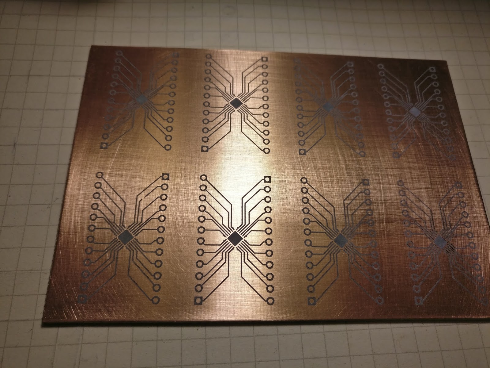
After you're done laminating just cool the substrate off so that it doesn't burn your hands and peel the paper off dry. The chalky layer of the photopaper peels off and stays on the board and this makes for a water-free, mess-free board ready to etch. In the picture below you can see a grid of circuits, these are adapters for a QFN-24 package IC that I wanted to plug into my breadboard. QFN-24 package is 4x4mm big and the tracks seen here are 0.2mm wide. Also you can see that there's a break in one of the tracks in the lower left, that's because of the damaged toner cartridge in my printer. And the board, as you see it, is right after I pulled the paper off. It is so much nicer, faster and cleaner than soaking it in water and rubbing the paper off.
With enough care you can get good results even without a laminator but it takes that extra effort, which makes the process tedious. Below picture is toner transfer using photo paper with a clothes iron and you can see that in some places the toner popped off. With a clothes iron you can also have a situation where you apply too much heat and pressure and the toner itself smudges, which is very bad for small features.

Next comes the etching stage. You can use whatever etching solution you like, my favorite is the copper chloride solution. Not many people know about this stuff yet it is in my opinion one of the most budget and DIY friendly etchants out there. You can make it by dropping some bare copper into some hydrochloric acid. This process is slow so you can add some peroxide to speed it up. Hydrochloric acid and peroxide is also an etching solution in itself but it's very short lived and expires quickly. Copper chloride works by absorbing oxygen from the atmosphere so it only gets stronger as it sits. Also this etchant is a gift that keeps on giving because the amount of it keeps constantly increasing so you never run out of it. Once the etchant becomes weak and bubbling air doesn't help that means you've depleted your solution of chloride ions and just need to add a splash of hydrochloric acid to replenish them, therefore the amount of etchant keeps increasing as you keep using it. Warming the etchant up also helps speed up the etching process. Also a big advantage of this etchant is that it doesn't stain as much as others, for example ferric chloride etchant is notorious for perma-staining everything it touches. Oh and did I mention that copper chloride is super cheap to make?
To etch your boards you need a container, for this I found a plastic container (on discount lucky me) that was the perfect size for the 100x70mm FR4 boards I was using. You want to be able to seal the container because spilling etchant everywhere is no fun. And there will be plenty chances to spill the etchant because you need to agitate it to make the etching process fast and consistent.

After etching you should have something like the picture below. I made a bit of a mistake with the board layout and did not add a copper ground pour. This is important for DIY PCB's because there's less copper to etch. In my case there was quite a lot so the etchant became overloaded and became slow, nevertheless I was able to complete the etch.

A good way to check the quality of your etching process is to place the board against a light source. In the picture below I used a homemade LED flashlight. You can see some dark spots where not all copper was etched away, that's because I was impatient and pulled the board out as soon as it was done, since the etchant was being overloaded and the process had slowed down quite a bit.

Now all that was left to do was to cut the boards out, drill the holes and solder everything together. In the picture below you can see everything done and plugged into an old beaten up breadboard that I used as a jig to make sure I solder my pins straight. This is also the part where my phone camera decided that I'm filming a mexican movie and gave this picture a yellow tinge to suit.

Below is a closeup of the board, you can even see the thickness of the copper layer. But you can also see some white crud under the IC and that's what happens when you clean rosin flux off with acetone, for whatever reason it leaves this white crap that's impossible to clean off.

And that's a job well done. You know, some people make the argument that making boards at home has become irrelevant with the rise of affordable services like PCBWay or JLCPCB but I know from experience that they take about a week to arrive from the time you order them and if all you need is an adapter or a one-off board are you really willing to let your project stall for an entire week? And that's with the expensive shipping, if you don't have the money you'll be waiting even longer. For example if I wanted to prototype with a QFN-24 on my breadboard I would need an adapter. You can buy adapters for SMD packages but are you really going to buy an adapter for every SMD package there is just in case you might use them someday? Or worse yet - deadbug *shudders*. A board like this took just a couple hours to make, looks much nicer than, say, deadbug and was super cheap. And if you're as impatient as me it's great to be able to prototype rapidly and have the board ready right now when you're at the peak of motivation.
Anyways, that's all for now and thanks for visiting my blog.


Komentarai
Rašyti komentarą